1.0 Purpose
Standardize operating procedures and operate continuous line pipe making machines correctly to ensure product quality.
2.0 Scope of Application
Operation of industrial piping, food hygiene piping, mechanical construction piping, heat exchanger piping, and condenser piping machines.
3.0 Production, repair, and disposal
The production, repair, and disposal of this production plan are the responsibility of the Production Technology Department, reviewed by the Quality Assurance Engineer, confirmed by relevant departments, and approved by the General Manager Implement after approval.
4.0 Implementation
a. Industrial piping process flow:
Unwinding → butt welding → forming → welding → rolling of inner weld seam (optional) → grinding → bright heat treatment → sizing → cutting to length
b. Process flow of food hygiene management:
Unwinding → butt welding → forming → welding → rolling of inner weld seam → grinding → sizing → sizing → external polishing → internal polishing
c. Mechanical structure pipe process flow:
Unwinding → butt welding → forming → welding → grinding → sizing → cutting to length → external polishing
d. Process flow of heat exchanger tubes:
Unwinding → butt welding → forming → welding → rolling of inner weld seam (optional) → grinding → bright heat treatment → sizing → sizing
e. Process flow of condenser tubes:
Unwinding → butt welding → forming → welding → rolling of inner weld seam (optional) → grinding → bright heat treatment → sizing → sizing
4.1 Unwinding
4.1.1 Technical parameters for uncoiling
a. Unwinding formation: Double arm rotary (1 unit), uncoiling (without power)
b. Single arm maximum load: 8T
c. The allowable range for the inner diameter of the steel coil is between 450 and 550 (mm)
d. Steel strip thickness range: 0.5-4.0 (mm)
e. Production range: diameter 12.7-108.00 (mm)
4.1.2 Key points and requirements for operation
a. Before driving and when taking over the shift, it is necessary to carefully check whether the equipment is in good condition and whether it operates flexibly and reliably.
b. According to the production plan, the steel coil labels are checked against the actual steel coil, and the confirmation content includes: product specifications, width
Thickness and material. Whether there are burrs on the steel coil and whether there are scratches on the edges, the appearance quality, etc. When installing the steel strip, attention should be paid to the shearing of the steel strip
The burrs should be facing upwards, based on the burrs on the inner wall of the formed steel strip.
c. After confirming the accuracy, hang the steel coil on the material rack and expand the expansion and contraction machine counterclockwise to the maximum position
Top up to the working object.
d. After installing the steel strip, expand the drum and install the baffle.
e. The braking system adopts handwheel adjustment, and its elasticity remains moderate.
f. When opening the steel strip, stand on both sides of the strip and be careful not to harm people.
4.1.3 Precautions
a. When lifting steel belts, the first thing to check is whether the lifting equipment is firm, safe and reliable.
b. When lifting, never damage the edges of the steel strip.
c. Clarify the direction of the steel strip to avoid rework.
4.2 Butt welding
4.2.1 Key points and requirements for operation:
a. AC arc welding is used for the connection of the head and tail of the steel strip.
b. When docking, it is necessary to ensure that the head and tail of the steel strip are aligned, level, and straight, without any overlapping or misalignment.
c. Select a reasonable current and welding rod based on the thickness of the steel strip.
d. After welding, it is necessary to ensure the firmness and reliability of the weld seam. The protruding parts of the weld seam should be smoothed with an angle grinder to ensure the mold is smooth Not scratched.
4.2.2 Precautions
a. During the welding process, it is necessary to ensure the cleanliness of the flat surface of the steel strip and not to use foot pedals.
b. During the welding process, pay attention to flammable materials around to prevent ignition.
c. When welding, if equipment and personal safety cannot be guaranteed, stop welding.
4.3 Forming
4.3.1 Process performance
a. Forming method: 360 ° bending forming.
b. Formed steel strip thickness: 0.5-4.0mm.
c. Width of formed steel strip: 40.3-341mm.
4.3.2 Operational requirements and key points
a. When the steel strip enters the forming machine, there should be no oil stains on the surface edges. If there are any, they must be cleaned up in a timely manner.
b. All roller surfaces in contact with the steel strip must be free from oil stains, dents, protrusions, scratches, and other factors. When installing the rolling mill,
Axial movement and radial runout are not allowed.
c. The center attribute of the vertical roller must be adjusted according to the horizontal roller and tightened.
d. The pipe seam coming from the 8th flat roller should ensure that the weld seam is in the "I" shape during welding and extrusion roller forming, and overlapping is not allowed
And misalignment.
e. The forming quality of the steel strip should be checked at all times, and there should be no indentation, scratches, waves, or other phenomena during the forming process of the steel strip,
If necessary, it should be handled according to the situation.
4.3.3 Precautions
a. Strengthen patrol inspections during the production process and promptly address any issues found.
b. Hands and feet should not come into contact with the rotating shaft and rolling mill to avoid crushing and injury.
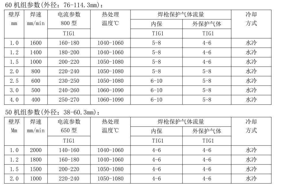
4.4 .4Welding process parameters
Welding method: argon arc welding (GTAW).
Protective gas: Ar gas, N2 gas with a purity of ≥ 99.99%, 93%+7% Ar, H2 mixed gas with a purity of ≥ 99.99%.
4.4.2 Operational requirements and key points
a. Check if the gas flow rate is within the required range.
b. Check if the pressure of the protective gas meets the process requirements.
c. The selection switches on the control panel must be placed in the correct positions. Check if the cooling water of the argon welding machine is flowing.
d. Check if the mold is contaminated with foreign objects.
e. Check if the welding gun position is appropriate and maintain verticality.
f. Check if the internal equipment of the welding gun is damaged and keep the tungsten rod clean.
g. Welding sequence: water supply → gas supply → current setting → arc welding → welding
4.4.3 Precautions
a. When spot welding, it is strictly prohibited to use high current to avoid burning through the steel strip and causing weld overlap.
b. Special attention should be paid to arcing eye contact and burns, and attention should be paid to electrical safety.
c. Argon welding machine welding gun and plasma welding gun, with a distance of 100mm between the two guns, should be regularly paid attention to whether the welding gun fusion position is produced during operation
Whether the deviation and gas flow rate are sufficient.
4.5 Rolling of internal weld seam
4.5.1 Operational requirements and key points
a. Adjust the angle of the core shaft so that the rollers on the core shaft are in a vertical position, so that the roller installation seat can smoothly move back and forth on it Move.
b. The production line is started, and the equipment is also started at the same time. Its actions are as follows:“
c. When pushing the oil cylinder forward, press down on the oil cylinder and lift it for one cycle. When pushing the oil cylinder back, press The lower oil cylinder does not move.
d. When the core rod cylinder is automatically turned on and off by the internal pulling equipment, the "press down cylinder" presses down and the cylinder exhausts. When the "pressing down oil cylinder" rises At start-up, the cylinder is inflated.
e. When the internal pulling equipment is manually turned on and off, the cylinder does not move.
4.5.2 Precautions
a. The pressing amount of the upper pressure roller should be appropriate to avoid causing the steel pipe to bend at that location or affecting the extension and descent of the hydraulic cylinder.
b. During the operation of the entire line, when there is a large inner weld bead caused by the concave or perforated weld seam on the surface of the steel pipe, it should be noted that Stop the operation of the device and raise the upper roller until the defect position passes before resuming operation.
4.6 6 Grinding
4.6.1 Operating procedure requirements
a. When installing the grinding wheel, pay attention to the rotation direction of the grinding wheel being in the same direction as the grinding machine.
b. Before starting the grinding machine, the protective cover should be installed, and the lower end of the grinding wheel should be 15-20mm higher than the weld seam.
c. After starting, gradually reduce to the grinding amount.
d. When repairing the grinding machine, it is necessary to regularly check the grinding quality of the weld seam. If there are any problems, adjust and handle them in a timely manner or replace the grinding wheel,Ensure the grinding quality of the weld seam.
4.6.2 Precautions
a. When repairing the grinding machine, it is forbidden to open the protective cover to prevent the wheel blades from flying out and injuring people.
 Mobile Access
 浙公网安备33050302000844